
博客

A console password:
configure t
line console 0
password cisco
login
end
A privileged password:
configure t
enable secret class
exit
Telnet password:
config t
line vty 0
password cnet201
login
end
network 192.168.1.0/24
config t
interface s0/0 (Site B linked to Site C Router)
ip address 192.168.1.1 255.255.255.0
clockrate 56000 (DCE Only)
no shutdown
end
config t
interface s0/0 (Site C linked to Site B Router)
ip address 192.168.1.2 255.255.255.0
no shutdown
end
Configure Routing Protocol
config t
router rip
version 2
network 192.168.1.0
network 192.168.1.0
no auto-summary
redistribute static
end
config t
interface s0/1 (Site B linked to Site A Router)
encapsulation frame-relay
frame-relay lmi-type ansi
clockrate 56000 (DCE Only)
no shutdown
end
config t
interface s0/1.1 point-to-point
ip address 192.168.1.31 255.255.255.0
frame-relay interface-dlci 103
interface s0/1.2 point-to-point
ip address 192.168.1.32 255.255.255.0
frame-relay interface-dlci 100
config t
interface f0/1
ip address 192.168.1.10 255.255.255.0
no shutdown
end
config t
interface loopback 0 (on Site A)
ip address 192.168.1.43 255.255.255.0
no shutdown
end
1, Cables required between the Router and Modem? Rollover cable
2, Cables required between the terminal/PC and Modem? Rollover cable
3, What type of connection do we have between the modem and router and modem and PC/Terminal? Parallel
Common “AT” commands:
- at enterkey
- ati4
- atdt (telephone number)
- +++ (to return to the modem command state) – shift +++
- ath (to disconnect hang-up the call)
1. Configure the London router AUX port to accept asynchronous connections.
London (config)# line aux 0
London(config-line)# password cisco
London(config-line)# login London(config-line)# speed 9600
London(config-line)# flowcontrol hardware
London(config-line)# stopbits 1
London(config-line)# modem inout
London(config-line)# transport input all
London(config-line)# exit
2. Issue a show line command to determine what line number has been associated with the AUX port. This lab will use line 65 for purposes of example. You must use whatever line your router has associated.
3. There are several ways to configure the modem. This lab will use a function called reverse telnet.
a. First you need to enable the vty passwords to allow telnet access.
London (config)# line vty 0 4
London(config-line)# password cisco
London(config-line)# login
b. Configure a loopback interface so that the router has at least one active interface.
London(config)# interface loopback 0
London(config-if)# ip address 192.168.1.1 255.255.255.255
c. Reverse telnet uses the port number 2000 + the AUX line number. So if the AUX port is associated with line 65, the reverse telnet port number would be 2065.
London# telnet 192.168.1.1 2065
This should open a reverse telnet session and establish communication with the modem. You should be prompted for a password. Type the password cisco, a session should begin with the modem.
NOTE: You will not receive a prompt from the modem.
4. Type the modem command: AT If you are communicating with the modem, it should respond with an OK.
5. Modems can use different command sets but some of the following are fairly standard for most modems.
AT&V - view the current configuration (Hayes modems)
ATI4 - view the cureent configuration (USR Sportster modems)
AT&F - restore parameters to factory defaults
ATS0=2 - configure modem to answer on second ring
ATL3 – adjusts speaker volume
AT&W – write new configuration to modem
6. After modem is configured with above parameters, suspend the reverse telnet session.
CTRL+Shift+6 (at the same time)
Press X
London# disconnect enterkey
Resp: closing connection to 192.168.1.1 [confirm] enterkey
Note: Another useful key stoke “control z” when logged into the router via HyperTerminal
7. On the host, go to HyperTerminal and select the modem from the Connect To window. Enter the number of the ADTRAN POTS port (Your instructor will give you this number).
NOTE: The most common mistake at this point is to dial yourself – this will end in a busy signal. Ensure you enter the phone number of the other modem.
NOTE: Cable between router 1 and PSTN/ISDN network Cloud (Adtran for this lab) is a RJ-45 straight-through cable
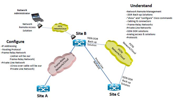
Objective
Configure an ISDN router to make a legacy dial-on-demand routing (DDR) call to another ISDN capable router.
When the DDR connection is successfully made, augment the configuration to specify that only http traffic will bring up the link.
Background/Preparation
In this lab, 2 ISDN routers are required An Adtran Atlas550 ISDN emulator is used to simulate the PSTN switch/ISDN cloud.
Cable a network similar to the one in the diagram above. The configuration output used in this lab is produced from Cisco series routers. Any other router used may produce slightly different output.
Step 1 Configure the routers
Configure all of the following according to the chart:
. • The hostname
. • The console password
. • The virtual terminal password
. • The enable secret password
Step 2 Define switch type and spid numbers
The switch type and spid numbers need to be specified on the routers.
Router 1 Tokyo
Router(config)# hostname Tokyo
Tokyo(config)# enable secret class
Tokyo(config)# isdn switch-type basic-ni
Tokyo(config)# interface fastethernet 0/0
Tokyo(config-if)# ip address 172.16.1.129 255.255.255.128
Tokyo(config-if)# no shutdown
Tokyo(config-if)# exit
Tokyo(config)# interface bri 0/0
Tokyo(config-if)# isdn spid1 51055512340001 5551234
Tokyo(config-if)# isdn spid2 51055512350001 5551235
Tokyo(config-if)# no shutdown
Tokyo(config)# interface loopback 0
Tokyo(config-if)# ip address 172.16.1.1 255.255.255.255
Tokyo(config)# interface loopback 1
Tokyo(config-if)# ip address 192.168.1.1 255.255.255.255
Tokyo(config)# interface serial 0/0
Tokyo(config-if)# ip address 192.168.2.65 255.255.255.252
Tokyo(config-if)# no shut
Router 2 Moscow
Router(config)# hostname Moscow
Moscow(config)#enable secret class
Moscow(config)# isdn switch-type basic-ni
Moscow(config)#interface fastethernet 0/0
Moscow(config-if)#ip address 172.16.3.129 255.255.255.128
Moscow(config-if)#no shutdown
Moscow(config-if)#exit
Moscow(config)#interface bri 0/0
Moscow(config-if)#isdn spid1 51055540000001 5554000
Moscow(config-if)#isdn spid2 51055540010001 5554001
Moscow(config-if)#no shutdown
Moscow(config)# interface loopback 0
Moscow(config-if)# ip address 172.16.4.1 255.255.255.255
Moscow(config)# interface loopback 1
Moscow(config-if)# ip address 192.168.4.1 255.255.255.255
Moscow(config)# interface serial 0/0
Moscow(config-if)# ip address 192.168.2.66 255.255.255.252
Moscow(config-if)# no shut
Step 3 Defining static routes for DDR
a. Use static and default routes instead of dynamic routing, in order to reduce the cost of the dialup connection. To configure a static route, the network address of the network to be reached must be known. The IP address of the next router on the path to this destination must be known as well.
Moscow# configure terminal
Moscow(config)#ip route 172.16.1.0 255.255.255.0 172.16.2.1 10
Moscow(config)#ip route 172.16.1.0 255.255.255.0 Serial0/0
Moscow(config)#ip route 192.168.1.0 255.255.255.0 172.16.2.1 10
Moscow(config)#ip route 192.168.1.0 255.255.255.0 Serial0/0
Tokyo# configure terminal
Tokyo(config)#ip route 172.16.3.0 255.255.255.0 172.16.2.2
Tokyo(config)#ip route 172.16.4.0 255.255.255.0 172.16.2.2
Tokyo(config)#ip route 192.168.3.0 255.255.255.0 Serial0/0
Tokyo(config)#ip route 192.168.3.0 255.255.255.0 172.16.2.2 10
Tokyo(config)#ip route 192.168.4.0 255.255.255.0 Serial0/0
Tokyo(config)#ip route 192.168.4.0 255.255.255.0 172.16.2.2 10
b. Perform a show IP route to verify routes exist.
Step 4 Specifying interesting traffic for DDR
Specify the traffic that will cause the DDR interface to dialup the remote router. For the moment, declare that all IP traffic is interesting. This is done using the dialer-list command:
Tokyo# configure terminal
Tokyo(config)# dialer-list 1 protocol ip list 1
Tokyo(config)# access-list 1 permit 172.16.0.0 0.0.255.255
Tokyo(config)# access-list 1 permit 192.168.0.0 0.0.255.255
Tokyo(config)# interface bri 0/0
Tokyo(config-if)# dialer-group 1
Tokyo(config-if)# end
Step 5 Configuring DDR dialer information
a. Configure the correct dialer information so that the dialer profile and dialer interface function correctly. This includes all of the following:
. • IP address information
. • PPP configuration
. • Name
. • Passwords
. • Dial number
Tokyo# configure terminal
Tokyo(config)# interface bri 0/0
Tokyo(config-if)# ip address 172.16.2.1 255.255.255.252
Tokyo(config-if)# no shut
b. Configure the PPP information:
Tokyo# configure terminal
Tokyo(config)# username Moscow password class
Tokyo(config)# interface bri 0/0
Tokyo(config-if)# encapsulation ppp
Tokyo(config-if)# ppp authentication chap
c. Configure the dial information:
Tokyo# configure terminal
Tokyo(config)# interface bri 0/0
Tokyo(config-if)# dialer idle-timeout 50
Tokyo(config-if)# dialer map ip 172.16.2.2 name Moscow 5554000
Tokyo(config-if)# dialer map ip 172.16.2.2 name Moscow 5554001
Step 6 Configuring DDR Dialer Information
Moscow# configure terminal
Moscow(config)#dialer-list 1 protocol ip list 1
Moscow(config)#access-list 1 permit 172.16.0.0 0.0.255.255
Moscow(config)#access-list 1 permit 192.168.0.0 0.0.255.255
Moscow(config)# username Tokyo password class
Moscow(config)# interface bri 0/0
Moscow(config-if)# ip address 172.16.2.2 255.255.255.252
Moscow(config-if)# dialer-group 1
Moscow(config-if)# encapsulation ppp
Moscow(config-if)# ppp authentication chap
Moscow(config-if)# dialer idle-timeout 50
Moscow(config-if)# dialer map ip 172.16.2.1 name Tokyo 5551234
Moscow(config-if)# dialer map ip 172.16.2.1 name Tokyo 5551235
Step 7 Configure dialer information
a. The dial information must specify the remote name of the remote router in the dialer profile. It must also specify the dial string, or phone number, to use to contact the remote device.
b. To configure the dial information on Tokyo, use the following:
Tokyo(config)# interface dialer 1
Tokyo(config-if)# dialer remote-name Moscow
Tokyo(config-if)# dialer string 5554000
Tokyo(config-if)# dialer string 5554001
c. To configure the dial information on Moscow, use the following:
Moscow(config-if)# interface dialer 0
Moscow(config-if)# dialer remote-name Tokyo
Moscow(config-if)# dialer string 5551234
Moscow(config-if)# dialer string 5551235
Step 8 Configure dialer timeouts
a. Configure a dialer idle-timeout of 60 seconds for each of the dialer interfaces:
Tokyo(config)# interface dialer 1
Tokyo(config-if)# dialer idle-timeout 10
b. Repeat these commands on Moscow.
Step 9 View the Tokyo router configuration
a. To view the configuration, use the show running-config command:
Tokyo#show running-config
b. What authentication is being used?
c. What are the dialer strings on the Tokyo router?
Step 10 Verifying the DDR Configuration
a. Now, generate some interesting traffic across the DDR link from both remote routers, Moscow and Tokyo, to verify that connections are made correctly and the dialer profiles are functioning:
Tokyo# ping 172.16.4.1
Tokyo# ping 192.168.4.1
b. Were the pings successful?
c. If not troubleshoot the router configuration.
d. Use the show dialer command to show us the reason for the call. This information is shown for each channel.
Tokyo# show dialer
e. Which dialer strings are associated with Dialer1?
f. What is the last status for dial string 5554000 in the Dialer1 readout?
g. Use the show interface command and note that the output shows that the interface is spoofing. This provides a mechanism for the interface to simulate an active state for internal processes, such as routing, on the router. The show interface command can also be used to display information about the B channel:
Tokyo# show interface bri 0/0
Upon completion of the previous steps, finish the lab by doing the following:
. • Logoff by typing exit
. • Turn the router off
. • Remove and store the cables and adapter

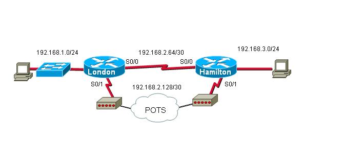
Steps:
1. Configure the London and Hamilton routers so that the hosts on the 2 LANs can ping each other using the serial links. Use any routing protocol. (recommended for this lab: static routing)
2. Configure loopback0 with ip address 192.168.4.1 255.255.255.255
3. Configure Ethernet or FastEthernet 0/0 with ip address 192.168.3.129 255.255.255.128
4. Configure an “enable password” for this router – password “cisco”
5. Configure “line vty 0 4” for remote logon access
Hamilton(config) line vty 0 4 Hamilton(config-line)# login
Hamilton(config-line)# password cisco
6. Configure the serial interface “S0/0 interface” on the Hamilton router for a connection to the London S0/0 synchronous connection. Hamilton(config)# interface s0/0
Hamilton(config-if)# ip address 192.168.2.66 255.255.255.252
Hamilton(config-if)# clockrate 9600
7. Configure a static router from the Hamilton router to the London network
Hamilton(config)# ip route 192.168.1.0 255.255.255.0 Serial0/0
8. Configure the serial interface “S0/1 interface” on the Hamilton router for an asynchronous connection to the modem. (back-up facility for this WAN network circuit design)
Hamilton(config)# interface s0/1
Hamilton(config-if)# physical-layer async
Hamilton(config-if)# ip address 192.168.2.129 255.255.255.252
Hamilton(config-if)# encapsulation ppp
Hamilton(config-if)# async mode dedicated
9. Configure Hamilton so that it can dial London on the s0/1 interface.
Hamilton(config-if)# dialer in-band
Hamilton(config-if)# dialer idle-timeout 10
Hamilton(config-if)# dialer wait-for-carrier-time 30
Hamilton(config-if)# dialer hold-queue 50
Hamilton(config-if)# dialer-group 1
10. Since the dial-up link is a low bandwidth connection, it is advisable to disable CDP so it does not waste bandwidth.
Hamilton(config-if)# no cdp enable
11. Configure a dialer map command to map the IP address of the destination router to the telephone number required to connect to it.
Hamilton(config-if)# dailer map ip 192.168.2.130 name london broadcast 555600x
x- is the last digit of telephone number for the destination end of the dial-up back-up WAN design. Please reference the Adtran Configuration Setting diagram.
12. Check to verify what line the router is associating with the asynchronous serial link. Then, configure the line.
Hamilton# show line - Note line association for the serial port
Hamilton(config)# line 2
Hamilton(config-line)# speed 9600
Hamilton(config-line)# flowcontrol hardware
Hamilton(config-line)# stopbits 1
Hamilton(config-line)# modem inout
Hamilton(config-line)# transport input all
Hamilton(config-line)# end
On the Hamilton router define “interesting” traffic. Interesting traffic is any IP traffic destined for the London router.
Hamilton(config)# access-list 1 permit 192.168.0.0 0.0.255.255
Hamilton(config)# dialer-list 1 protocol ip list 1
14. Configure a static route from Hamilton to London. This static route will only be used if the link from S0/0 to London’s s0/0 goes down. You would use a default route instead of a routing protocol because the frequent "conversations" of the routing protocol would keep the dial-up link active even if there was no " payload" traffic.
Hamilton(config)# ip route 192.168.0.0 255.255.0.0 192.168.2.130
15. Save the Hamilton configuration.
16. Configure the London router as follows:
Configure an “enable password” for this router – password “cisco”
London(config)# interface s0/0
London(config-if)# ip address 192.168.2.65 255.255.255.252
London(config-if)# end
London(config)# interface loopback 0
London(config-if)# ip address 192.168.1.1 255.255.255.255
London(config-if)# end
London(config)# interface FastEthernet 0/0
London(config-if)# ip address 192.168.1.129 255.255.255.128
London(config-if)# end
London(config)# interface s0/1
London(config-if)# physical-layer async
London(config-if)# ip address 192.168.2.130 255.255.255.252
London(config-if)# encapsulation ppp
London(config-if)# async mode dedicated
London(config-if)# no cdp enable
London(config-if)# end
London(config)# line 2
London(config-line)# speed 9600
London(config-line)# flowcontrol hardware
London(config-line)# stopbits 1
London(config-line)# modem inout
London(config-line)# transport input all
London(config-line)# end
London(config)# line vty 0 4
London(config-line)# login
London(config-line)# password cisco
London(config-line)# end
Static route configurations for the London router:
London(config)# ip route 192.168.3.0 255.255.255.0 Serial0/0
London(config) # ip route 192.168.3.0 255.255.255.0 Serial0/1 10
London(config) # ip route 192.168.4.0 255.255.255.0 Serial0/0
London(config) # ip route 192.168.4.0 255.255.255.0 Serial0/1 10
B: Explain why we have the number “10” at the end of 2 of the static route statements above.
c. Ping from the host on Hamilton to the host on London. The first “ping” will fail but it should activate the Hamilton router to dial the London router. Once connectivity has been established between the routers, execute another ping. This one should be successful.
* The connection from the modem to the AUX port requires a console cable
* You would only configure one router to be the dialing router. If both routers were configured to " dail" each other and the primary line went down, both sides would dial simultaneously and each would receive a busy signal. So one side becomes the " dailer" like the hamilton, and ther other side is the ansering party.To check the ISDN BRI status, issue: # show isdn status
2. There are 9 different switch types are availabe. by # isdn switch-type ?
3. To configure therouter with National ISDN-1 type: #isdn switch-gype basic-ni
4. To send the SPID VALUES the interface must be reset. by command # clear interface bri 0/0
5. Review activity on the ISDN interface using: #show idn active

WAN LAB EXAM -
Router A - Kelvin
int s0/0
encapsulation frame-relay
frame-relay lmi-type ansi
no shutdown
interface s0/0.1 point-to-point
ip address 192.168.1.1 255.255.255.0
frame-relay interface-dlci 102
show frame pvc
router rip
version 2
network 192.168.1.0
Router B - Akbar
int s0/0
encapsulation frame-relay
frame-relay lmi-type ansi
no shutdown
interface s0/0.1 point-to-point
ip address 192.168.1.2 255.255.255.0
frame-relay interface-dlci 201
int s0/1
ip address 192.168.2.2 255.255.255.0
(clockrate if im dce 64000)
no shutdown
encapsulation ppp
exit
config#username Joey password cisco
interface s0/1
ppp authentication chap
router rip
version 2
network 192.168.1.0
network 192.168.2.0
Router C - Joey
int s0/1
ip address 192.168.2.1 255.255.255.0
(clockrate if im dce 64000)
no shutdown
encapsulation ppp
exit
config#username Akbar password cisco
interface s0/1
ppp authentication chap
router rip
version 2
network 192.168.2.0
Configure the Dublin router serial interface as follows:
Dublin(config)# interface serial 0/0
Dublin(config-if)# ip address 192.168.15.2 255.255.255.0
Dublin(config-if)# no shutdown
Dublin(config-if)# exit
Dublin(config)# exit
Step 3 Configure the Washington s0/0 interface as shown
Configure the Washington router serial interface as follows:
Washington(config)# interface serial 0/0
Washington(config-if)# ip address 192.168.15.1 255.255.255.0
Washington(config-if)# clock rate 64000
Washington(config-if)# no shutdown
Washington(config-if)# exit
Washington(config)# exit
Step 4 Save the configurations
Washington# copy running-config startup-config
Dublin# copy running-config startup-config
Step 5 Enter the command show interface serial 0/0 on the Washington router
Washington# show interface serial 0/0
Change the encapsulation type to PPP by typing encapsulation ppp at the interface serial 0/0 configuration mode prompt on both routers.
Washington(config-if)# encapsulation ppp
Dublin(config-if)# encapsulation ppp
Step 10 Configure PPP authentication on the Washington router
Configure the username and password on the Washington router. The passwords must be the same on both routers. The username must reflect the other routers hostname exactly. The password and user names are case sensitive:
Washington(config)# username Dublin password cisco
Washington(config)# interface serial 0/0
Washington(config-if)# ppp authentication chap
default Encapsulation type = HDLC
*show interface serial ----显示PPP configuration
*debug ppp 检查PPP的实时工作过程
debug ppp packets 显示发送和接收时的数据包
debug ppp error
debug ppp chap 显示CHAP 数据包的交换
debug ppp authentication 可以观察验证的过程
degug ppp negotiation 可以观察连接的建立和验证的过程